Architecture
In this section, we will explore the architecture of the HashiCorp Validated Design for Vault Enterprise. This architecture is designed to provide a highly-available, scalable, and secure Vault Enterprise deployment that is suitable for production workloads, and is intended to be used as a starting point for your own Vault Enterprise deployments. First, we will discuss the components that make up a single Vault cluster and its related infrastructure. We will then add a secondary Vault cluster, culminating in a multi-cluster architecture that can be used to provide both high-availability as well as disaster recovery for your Vault Enterprise deployment.
The primary components that make up a single Vault cluster are:
- Cluster of Vault nodes
- Load balancer
- Snapshot storage (backups)
- Seal mechanism
- Audit device(s)
Cluster
Vault uses a client/server architecture. The Vault server hosts an API, which Vault clients can communicate with via HTTP/HTTPS. Through client requests to the API, data is read from or written to the data storage backend.
Integrated storage
While Vault Enterprise has two data storage backends available, this architecture uses the integrated storage backend. integrated storage is based on the Raft consensus algorithm(opens in new tab), and is built directly into the Vault binary. Because of this, the API and storage layers of Vault run on the same machine. There is no need to install additional software in order to use the integrated storage backend.
Clustering
Vault supports multi-node deployment for high-availability. This mode protects against outages by configuring multiple Vault nodes to operate as a single Vault cluster. To ensure this high-availability, nodes within a cluster should always be spread across multiple availability zones.
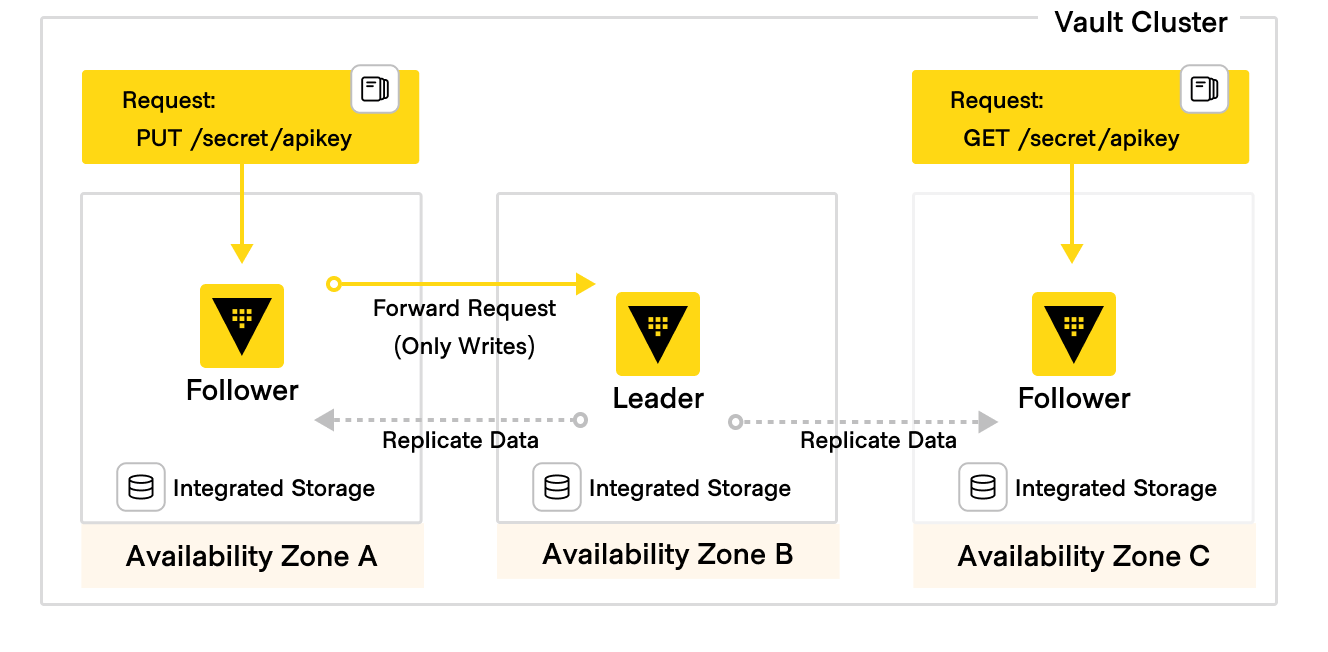
When using integrated storage, the cluster is bootstrapped during the initialization process. Initial bootstrapping results in a cluster of 1 node. This node is the active node (also known as the leader). Additional nodes can then be joined to the active node as standby nodes (also known as followers). Once a standby node has successfully joined the cluster, data from the active node will begin to replicate to it.
In a Vault cluster, only the active node performs write operations against the storage backend. Standby nodes can perform reads against storage and forward writes to the active node. This functionality is called performance standby mode, and is enabled by default for all standby nodes when using integrated storage on Vault Enterprise(opens in new tab).
A Vault cluster must maintain quorum in order to continue servicing requests. Because of this, nodes should be spread across availability zones to increase fault tolerance.
 Figure 1: HVD Vault HA 3 nodes diagram
Voting nodes vs non-voting nodes
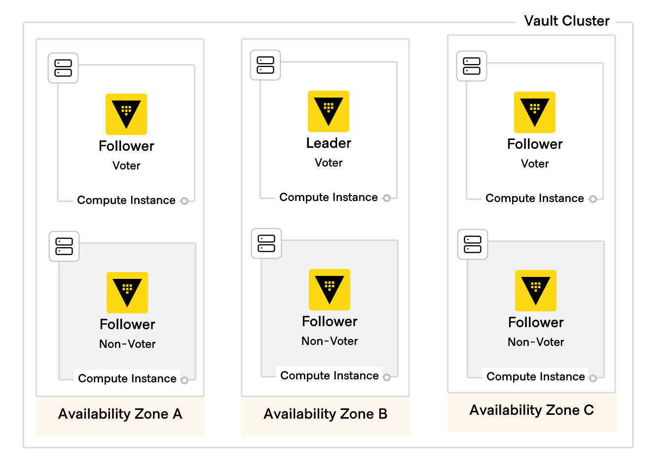
By default, standby nodes are also voters. If the active node becomes unavailable, a new active node is chosen by and among the remaining standby nodes. However, standby nodes can also be specified as non-voters. Non-voting nodes also act as data replication targets, but do not contribute to the quorum count.
Autopilot
A non-voting node can be be promoted to a voting node through the use of Vault Enterprise's Autopilot(opens in new tab) functionality. In addition to this, autopilot also enables several automated workflows for managing integrated storage clusters, including server stabilization, automated upgrades, and redundancy zones. For more information, see the HashiCorp documentation on Vault Enterprise Autopilot(opens in new tab).
Redundancy zones
Using Vault Enterprise Redundancy Zones(opens in new tab), the Vault cluster leverages a pair of nodes in each availability zone, with one node configured as a voter and the other as a non-voter. If one voter becomes unavailable (regardless of whether it is an active node or a standby node), autopilot will promote its non-voting partner to take its place as a voter. This architecture gives high availability both within an availability zone as well as across availability zones, ensuring that (n+1)/2 redundancy is maintained at all times.
 Figure 2: HVD Vault HA 6 nodes redundancy zones diagram
Load balancing
Use a layer 4 load balancer capable of handling TCP traffic to direct Vault client requests to the server nodes within your Vault cluster. Using a load balancer reduces the amount of static configuration on Vault clients, as they will access the service via the load-balanced endpoint, rather than sending requests directly to an individual node. Any request sent to a standby node that requires an active node to process (e.g. write requests) will be proxied by the standby node to the active node.
Vault server nodes also perform server-to-server communication to other nodes in the cluster over 8201/tcp. This is used for functions critical to the integrity of the cluster itself, such as data replication or active node election. Unlike client requests, server-to-server traffic should not be load-balanced. Instead, each node must be able to communicate directly with all other nodes in the cluster.
Tip
Vault also automatically enforces encrypted communication between Vault nodes via an additional port separate from client communication. This communication is internal to Vault and does not require additional certificates or management.
TLS
To ensure the integrity and privacy of transmitted secrets, communications between Vault clients and Vault servers should be secured using TLS certificates that you trust. Do not manage the TLS certificate for the Vault cluster on the load balancer. Instead, the certificate chain (i.e. a public certificate, private key, and certificate authority bundle from a trusted certificate authority) should be distributed onto the Vault nodes themselves, and the load balancer should be configured to pass through TLS connections to Vault nodes directly. Terminating TLS connections at the Vault servers offers enhanced security by ensuring that a client request remains encrypted end-to-end, reducing the attack surface for potential eavesdropping or data tampering.
Warning
Avoid using self-signed certificates for production Vault workloads.
Backup snapshot storage
Automated snapshots should be saved to a storage medium, separate from the storage used for the Vault storage backend. Snapshot storage does not require the same high IO-throughput requirements as the rest of Vault, but it should be durable enough to ensure fast retrieval and restoration of backups when needed. To satisfy this requirement, use an object storage system such as AWS S3, or a network-mounted filesystem, such as NFS. Configuring the snapshots themselves, their frequency, and other operational considerations can be found in Vault: Operating Guide for Adoption.
Sealing and unsealing
In order to protect itself and your data, Vault will seal itself under certain conditions, such as during a loss of quorum.
Sealing prevents control of Vault from falling into the hands of a single actor. By default, when Vault becomes sealed, it can be unsealed by manually submitting enough unseal key shards, which are created when the Vault cluster is first initialized.
Because this process is manual, it can become suboptimal when you have many Vault clusters, as there are now many different key holders with many different keys. For Vault Enterprise deployments, we instead recommend configuring an auto-unseal mechanism. Auto-unseal eliminates the need for manual intervention, and reduces the operational complexity of keeping Vault unseal keys secure.
Auto-Unseal using cloud-based KMS services
The most common method of auto-unsealing is through the use of a cloud-based key management service (KMS) system, such as AWS KMS(opens in new tab), Azure Key Vault(opens in new tab), or GCP Cloud KMS(opens in new tab). For more information, refer to the HashiCorp Documentation on Auto Unseal(opens in new tab).
Warning
Important note About recovery keys:
Recovery keys are purely an authorization mechanism, and cannot decrypt the root key. This means that recovery keys are not sufficient to unseal Vault if the auto unseal mechanism is not working. Using auto-unseal creates a strict Vault lifecycle dependency on the underlying seal mechanism. If the seal mechanism (such as the cloud KMS key) becomes unavailable, or is deleted before the seal is migrated, there is no ability to recover access to the Vault cluster until the seal mechanism becomes available again. If the seal mechanism or its keys are permanently deleted, then the Vault cluster cannot be recovered, even from backups. To mitigate this risk, we recommend careful controls around management of the seal mechanism, such as AWS Service Control Policies.
If your architecture will include any secondary Vault clusters, configure these clusters with a different seal mechanism than that of the primary. This ensures that if the primary cluster becomes unrecoverable due to an issue with its seal mechanism, the secondary cluster can still be accessed.
Regardless of the seal mechanism you choose to deploy with your Vault cluster, we recommend encrypting the key shares and initial root token value at initialization time with user-supplied public keys. Operators can generate these keys from OpenPGP-compliant software such as GNU Privacy Guard (GPG)(opens in new tab).
Auto-unseal using a hardware security module
As an alternative to cloud-based KMS, you can use a hardware security module(opens in new tab) (HSM) to provide a secure auto-unsealing method for Vault. This method is primarily recommended for certain private datacenter environments in which the use of cloud-based KMS services is not available or not suitable for the deployment. This method enables Vault to use HSM devices (supporting PKCS11 operations) to encrypt the root key. Vault stores this HSM-encrypted root key in internal storage, and the HSM device automatically decrypts it.
HSM automatic unsealing with Vault involves using the HSM to encrypt and store Vault's unseal key. Upon Vault startup, instead of manually entering unseal keys, the unseal key is automatically decrypted by the HSM. This process ensures that the unsealing procedure is both secure and automated, reducing the risk of human error.
In addition to the unseal key managed by the HSM, Vault will also generate recovery keys to authorize human recovery operations on the Vault cluster. Because a quorum of recovery key shares can be used to generate a new root token, and because root tokens can grant extensive access to Vault, PGP encryption should always be used to protect the returned recovery key shares(opens in new tab). This ensures that even if recovery keys are exposed, they remain encrypted and unusable without the corresponding PGP key.
Both rekeying the root key and rotation of the underlying data encryption key are supported when using an HSM(opens in new tab).
Audit devices
Audit devices(opens in new tab) collect and keep a detailed log of all Vault requests and corresponding responses. Vault operators can use these logs to ensure that Vault is being used in a compliant manner, and to provide an audit trail for forensic analysis in the event of a security incident.To ensure the availability of audit log data, configure Vault to use multiple audit devices. Writing an additional copy of audit log data to a separate device can help prevent data loss in the event one device becomes unavailable, and can also help guard against data tampering. More information on the configuration and management of audit devices and audit logs can be found in Vault: Operating Guide for Adoption.
Cluster architecture summary
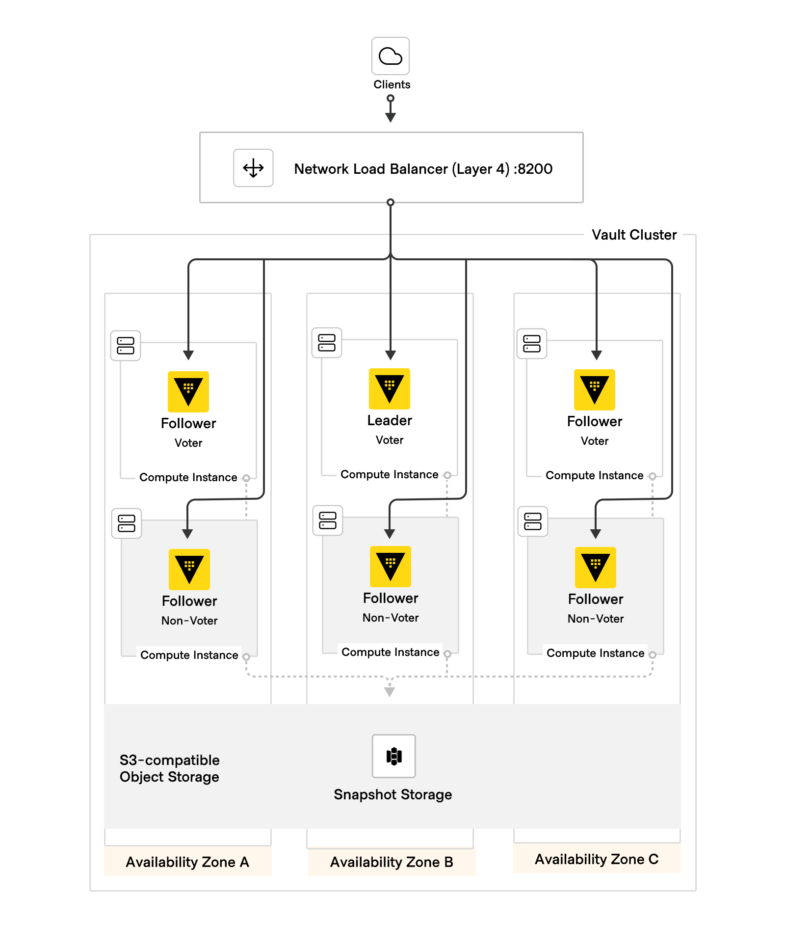
To summarize, the HashiCorp Validated Design for a Vault Enterprise cluster architecture is made up of the following components:
- 6 Vault servers, deployed across three availability zones within a geographic region.
- Using a redundancy zones topology, each node is configured as a voter or non-voter, with one of each per availability zone.
- Locally-attached, high-IO storage for Vault's integrated storage.
- A layer 4 (TCP) load balancer, with TLS certificates distributed to the Vault nodes.
- An object storage or network filesystem destination for storing automated snapshots.
- An auto-unseal mechanism, such as a cloud-based KMS or an HSM.
- Audit devices, configured to write to multiple destinations.
 Figure 3: HVD Vault cluster architecture diagram
Disaster recovery secondary cluster
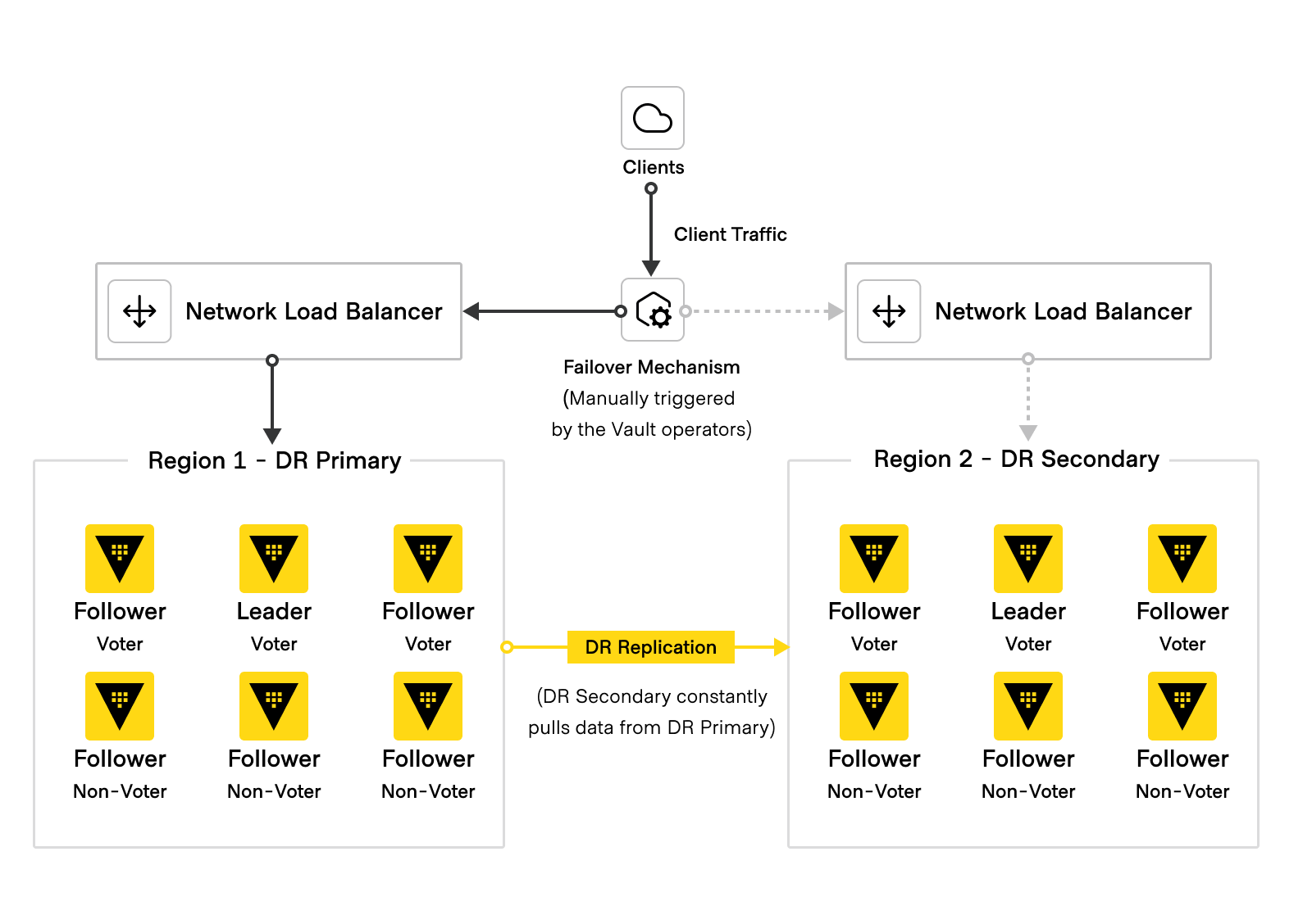
Disaster recovery (DR) secondary clusters are essentially warm standbys of the primary Vault cluster, and are used to provide continuity of service in the event of a cluster-wide outage. They do not service any of their own requests, but instead replicate data from the primary cluster. The replicated data not only includes secrets, but also tokens and leases.
If the primary cluster becomes unavailable, Vault operators can manually fail over to the DR secondary cluster by promoting it to become the primary. This procedure restores access to the Vault service and its secrets data, so that clients can reconnect to Vault without having to re-authenticate.
DR secondary clusters share the same fundamental architecture as primary clusters, including related components such as network load-balancing, seal mechanisms, and audit devices. DR secondary clusters should always be equally sized in order to accept the same volume of requests as the primary.
DR secondary clusters are typically placed in different geographical regions than their primary clusters to guard against region-level outages, though this is not a requirement. There must be network connectivity between these regions to allow for continuous data replication.
Automated snapshots cannot be configured for DR secondary clusters before promotion. Vault operators can instead take manual snapshots if desired(opens in new tab).
The DR secondary cluster should also use auto-unseal, encrypted with a KMS key different from the one used on the primary cluster. After replication is enabled on the DR secondary cluster, the primary's keyring (which contains the recovery keys) are copied to the DR secondary as part of the bootstrapping process. If the secondary cluster also uses KMS auto-unseal, it utilizes the primary cluster's recovery keys and configuration (e.g., number of fragments and key share threshold). This can be changed with manual configuration on the DR secondary cluster. For more information, see the HashiCorp Documentation on Vault Enterprise Replication(opens in new tab) and Vault Replication Internals(opens in new tab).
Failover mechanism
The promotion of a DR secondary cluster to a primary cluster is a manual process.
The process of promoting and demoting Vault clusters is a non-trivial operation. If Vault briefly encountered service unavailability and the failover process was automated, this could cause unintentional data loss and/or data consistency issues.
Vault operates in an active-passive configuration, meaning that only one cluster is the source of truth for all shared secrets in an environment. This mitigates the split-brain problem in which multiple Vault clusters could separately manage the same secrets. To ensure that one cluster is always the source of truth, the standard DR failover promotes a DR cluster to serve all client requests. The demoted cluster does not attempt to immediately reconnect to a DR primary cluster, but maintains its current dataset so that Vault operators can reconnect it and update it later(opens in new tab).
Because DR secondary clusters do not service any client requests, they only become active when operators promote DR replicas and failover client requests. However, clients should not need to reconfigure how they communicate with Vault. Use an additional routing mechanism that can route clients to the active primary cluster, regardless of region. Examples of this include, but are not limited to:
- HashiCorp Consul(opens in new tab)
- Amazon Route53 DNS Failover(opens in new tab)
- Azure Traffic Manager(opens in new tab)
- Google Cloud DNS with HTTP(S) Load Balancer(opens in new tab)
- F5 Global Server Load Balancing (GSLB)(opens in new tab)
The following diagram illustrates the complete multi-cluster architecture as described above:
 Figure 4: HVD Vault Disaster Recovery Diagram
We will discuss each of these components and their configuration in more detail in the next section.